Functional explanation of the pianola
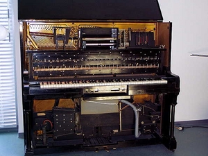
The "pianola" is an automatic piano - the instrument shown in the picture on the right was built in 1915. Instruments of this type are controlled by a vacuum system that is powered by bellows operated either manually or by means of a motor. The pneumatic system of the instrument described in the following is powered by a motor.
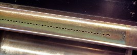
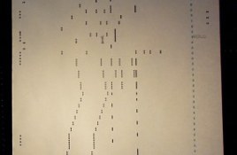
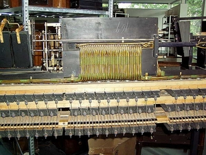
The piano roll is a strip of paper, many meters long, with holes punched in rows. Single holes or sequences of holes represent notes. This paper strip moves over a pickup bar with 88 openings (one for each key of the piano). In addition to these, this pickup contains additional openings which are used to control the pedals, the attack and the like.Clearly visible in the picture of the right are the yellow colored lead tubes that connect the pickup bar with the pneumatic amplifiers. These amplifiers are called "relays" and amplify the tiny differential pressures delivered by the pickup mechanism sufficiently to actuate the keys and pedals of the piano.
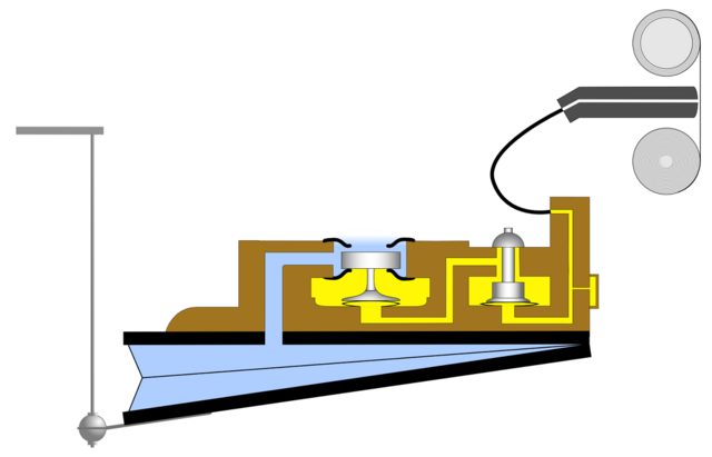
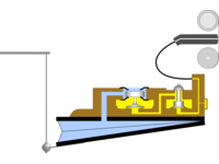
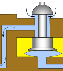
Schematic diagram of a single amplifier/actuator (relay) element (enlarge image)
Picture 1: Quiescent state
The schematic diagram shows one relay element. 88 of these are necessary to control all of the piano's keys. Due to their size, these 88 relays are mounted in three rows. Yellow color denotes part of the vacuum system while blue marked areas are at atmospheric pressure.
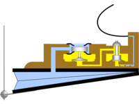
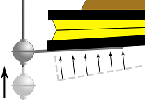
Picture 2: Hole in the piano roll, air enters the pickup bar
A hole in the piano roll allows air to enter the corresponding hole in the pickup bar. A small "pillow" located under the right valve of the relay is inflated by this stream of air which in turn opens the valve.
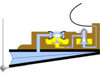
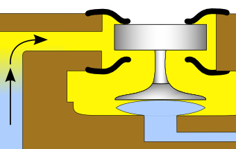
Picture 3: Amplification:
This right valve allows air to enter the left part of the relay which is built in a similar way. Another "pillow" actuates the left valve which is much bigger than the left valve and thus allows more air to flow. These two valves in fact act like an amplifier: The small pressure difference sensed by the pickup bar controls the first (right) valve which acts as a first amplifier stage. This controls the second (left) valve which acts as a power amplifier operating the the bellow shown below the relay unit.
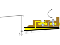
Picture 4: Contracting the bellow
The left valve of the relay connects the bellow located under the relay block with the evacuated part of the pneumatic system. When activated, this valve will cause the bellow to contract which in turn moves the corresponding key of the piano.
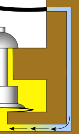
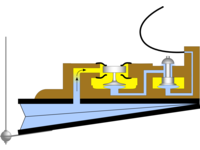
Picture 5: Preview of a tone
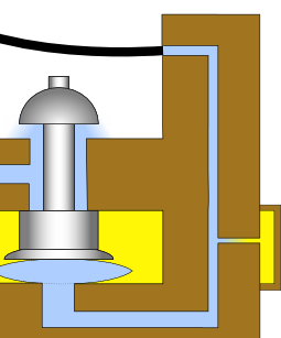
Without additional hardware, the bellow would stay in the contracted state after being actuated once. Thus, some means are necessary to release the bellow after a note and ready the system to play the next note. If there is no hole in the piano roll following the hole which actuated the bellow, the bellow must be returned to its inflated state as quickly as possible.
The picture on the right shows a small connection between the tube coming from the pickup strip and the vacuum system on the far right. This connection has a very small diameter so that it does not negatively affect the inrushing air current from the pickup bar when a hole is detected. If there is no hole, this connection withdraws the remaining air at atmospheric pressure from the right valve system thus closing this valve which, in turn, will close the second valve, which will eventually cause the bellow to inflate again. Now the pianola is ready to play the next note.
The pianola is able to play pieces which were impossible to play for a human player. Accordingly, there are pieces composed for the pianolo exclusively (like the "Studies for Player Piano" by Conlon Nancarrow). It is impressive to see what can be done by more or less simple mechanical systems.
